Why Most Remote Network Deployments Fail Before They Start
A CCTV integrator in rural Indonesia once sent us a quote that fell apart at the last moment. The wireless bridges were spec’d correctly. The poles were in place. The site survey was done. Then the client asked one question: “Where does the power come from?”
Trenching armored cable 300 m uphill to an isolated camera pole would have cost three times the hardware budget. The project stalled for six months.
The integrator eventually solved it with a solar kit and a low-power wireless bridge. The link came up in one day. It has been running without intervention for over two years.
This guide covers everything needed to replicate that outcome: what a solar-powered wireless bridge actually is, which applications it fits, how to size the solar system correctly, which MossLink models to use, and the common mistakes that cause systems to fail in the first rainy season.
No grid power. No trenching. No recurring electricity cost. Just a working link.
What Is a Solar-Powered Point-to-Point Wireless Bridge?
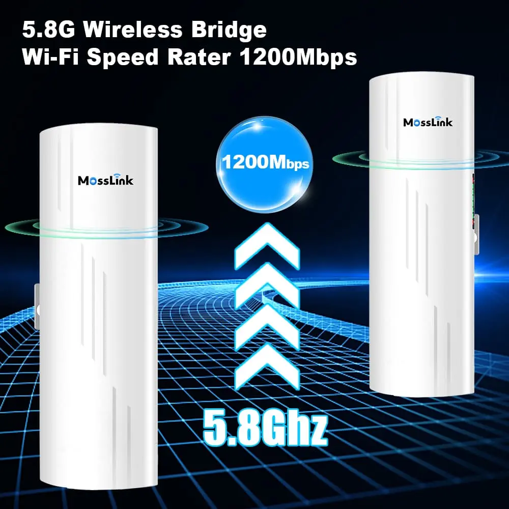
A point-to-point (PtP) wireless bridge creates a dedicated radio link between two fixed locations, extending an Ethernet network across distances that cable cannot reach. Unlike a Wi-Fi access point — which broadcasts signal in all directions for nearby clients — a PtP bridge uses a high-gain directional antenna aimed at a specific endpoint. All radio energy is focused along that beam, enabling reliable links from 500 m to 35 km.
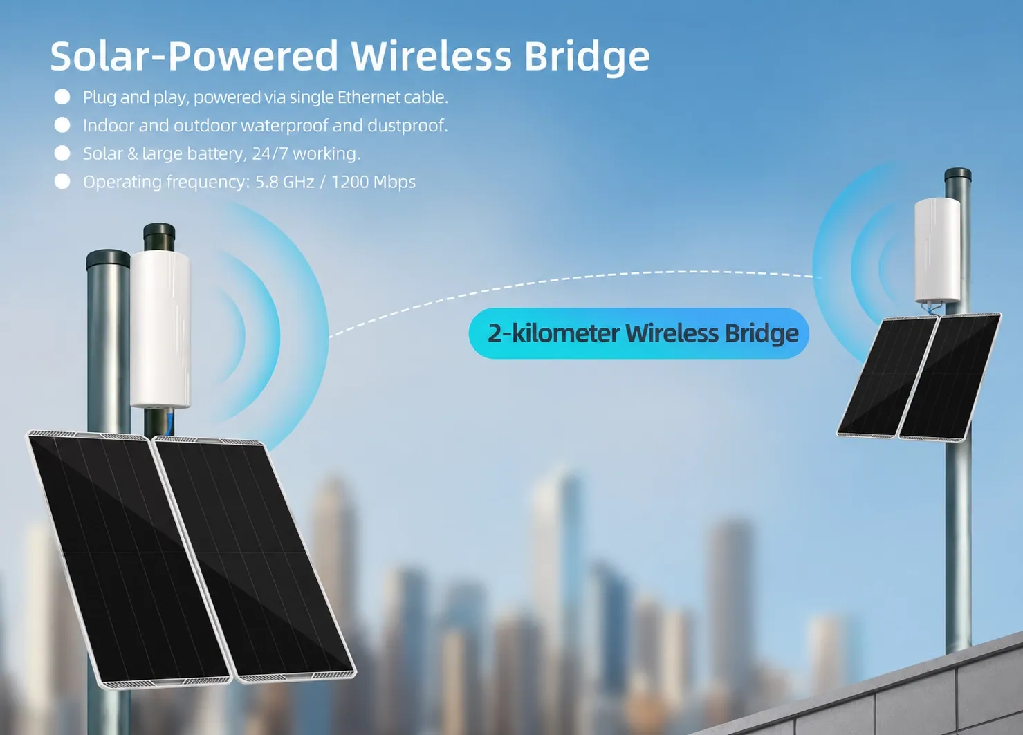
A solar wireless bridge adds an off-grid power system: a monocrystalline solar panel charges a lithium battery during daylight hours, and the battery powers the bridge continuously — including through the night and during overcast periods.
The complete system has four components:
| Component | Function |
|---|---|
| Solar panel | Converts sunlight to DC electricity (12V) |
| Charge controller | Regulates charging to protect battery life |
| Lithium battery | Stores energy for overnight and cloudy-day operation |
| Wireless bridge | The network device itself, powered via DC or passive PoE |
The critical difference from a standard Wi-Fi AP: A PtP bridge uses a directional antenna with 12–29 dBi gain, focused into a narrow beam toward the remote end. This concentrates all signal energy along the link path, allowing the radio to reach across kilometers of open terrain with the same transmit power that a typical AP scatters in all directions within a single room.
MossLink’s bridge lineup spans multiple performance tiers for solar deployments:
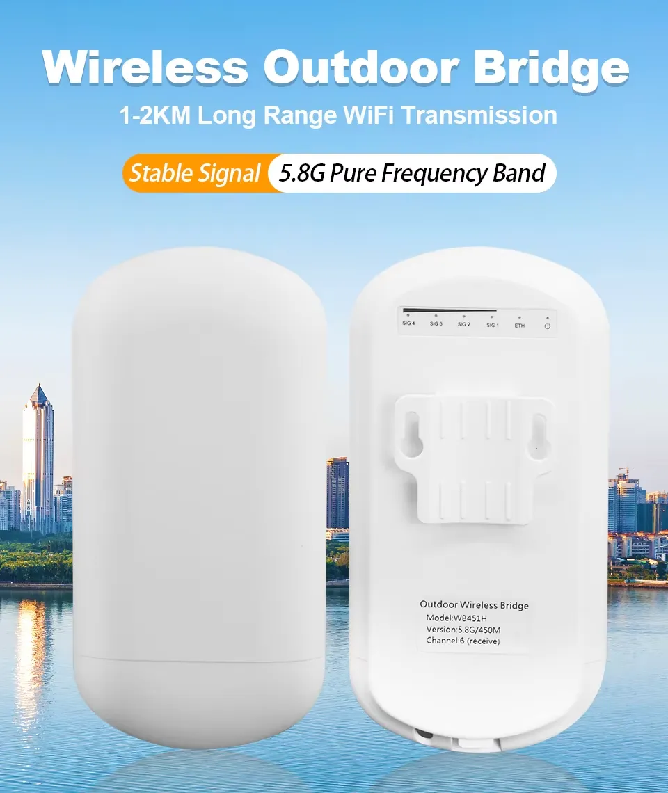
- WB451H — 5.8GHz, 450Mbps, 2km range, <3W power draw — ideal for short-range camera backhaul
- WB620H — 5.8GHz, 750Mbps actual, 5km range, <3W — mid-range CCTV and campus links
- WB5axH6-20 — Wi-Fi 6, 900+ Mbps, 16km range, <10W, 12V DC direct input — ISP relay and industrial backbone
- WB5axH6-35 — 29dBi dish, 1200Mbps, 35km range, IP67 — rural broadband and tower backhaul
Key Benefits of Solar-Powered Wireless Bridges
No electrical infrastructure required
The single biggest deployment blocker at remote sites is not coverage — it is power. Solar removes that constraint entirely. A bridge on a highway surveillance pole, a mountaintop ISP relay, or a construction site gate can be operational on the same day it is physically installed.
Cost comparison vs. alternatives
| Solar + Wireless Bridge | Armored Cable + Wired | 4G/5G Cellular | |
|---|---|---|---|
| Installation | Hours, no trenching | Days to weeks of civil work | Hours |
| Hardware cost | $200–$800 (one-time) | $500–$5,000+ per 100m run | $100–$300 |
| Monthly operating cost | $0 | Electricity only | $30–$150/month data |
| Throughput | 300–900+ Mbps | 1 Gbps | 10–100 Mbps |
| Off-grid capable | Yes | No | Coverage-dependent |
| Latency | <5ms | <1ms | 20–80ms |
| Reliability | High (IP65/IP67) | High | Variable (signal/weather) |
At a deployment lasting more than 12 months, the cellular monthly data cost alone typically exceeds the entire solar kit cost.
High reliability in harsh conditions
MossLink outdoor bridges carry IP65 or IP67 weatherproofing ratings. IP67 means the enclosure is fully dust-tight and survives submersion to 1 m — irrelevant for normal operation, but it means rain, condensation, and high humidity cannot reach internal components. The operating temperature range of -40°C to +70°C covers everything from alpine relay nodes to Middle Eastern desert surveillance posts.
Low power consumption enables smaller, cheaper solar kits
The WB451H and WB620H both draw less than 3W. A single 30W panel with a 30Ah battery can power one of these bridges continuously — the entire kit weighing under 6kg and mountable on the same pole as the bridge. This is the critical enabling factor for practical solar deployment: equipment that sips power instead of demanding large, expensive panels.
Zero ongoing energy cost, environmentally sustainable
After the initial hardware investment, operating cost is zero. At scale — a rural ISP with 20 relay nodes, or a CCTV integrator maintaining 50 remote sites — eliminating electricity infrastructure from every node represents a significant lifetime cost difference.
Typical Application Scenarios
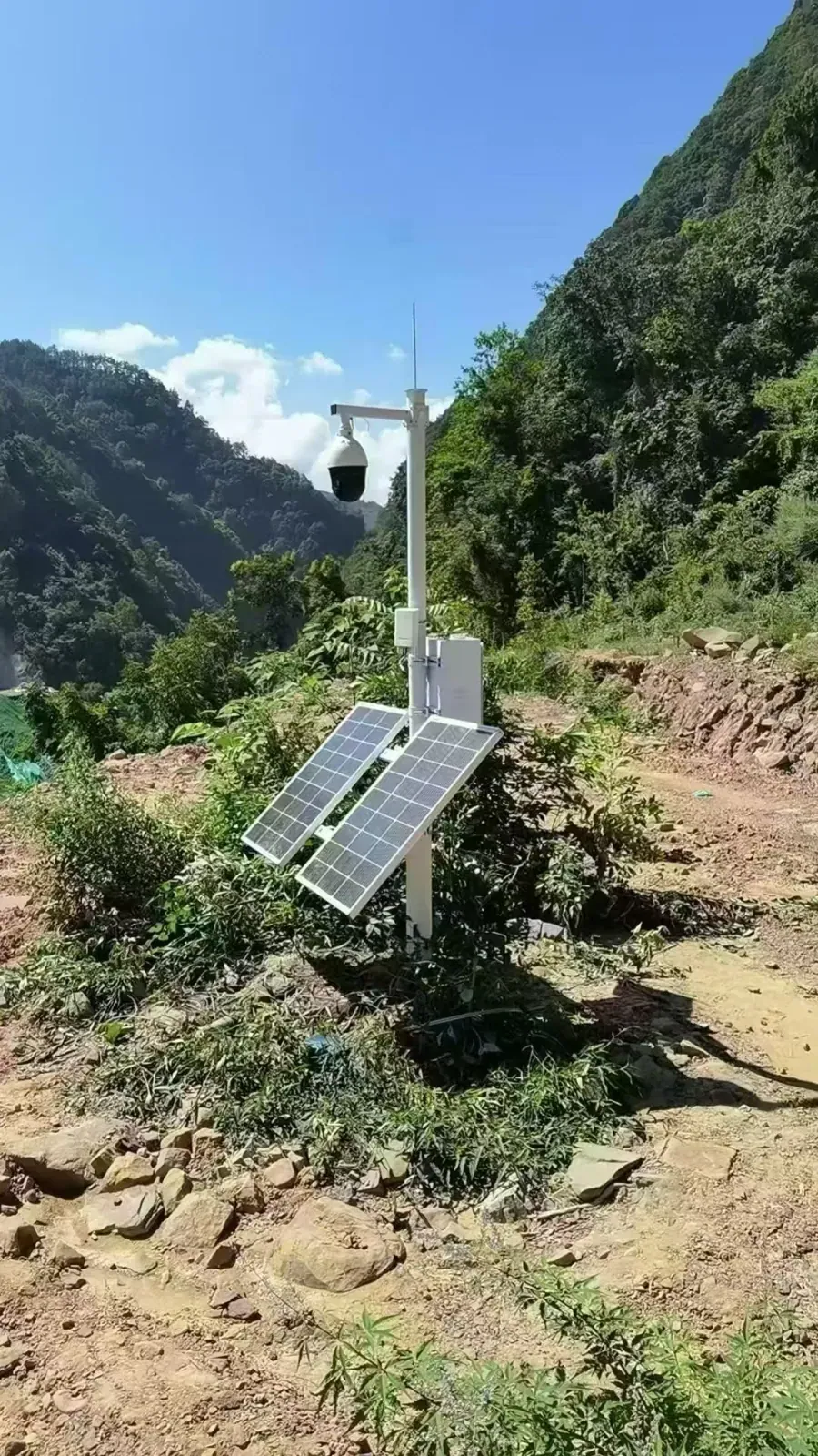
Remote CCTV surveillance — The most common solar bridge application. A single WB451H pair (<3W per unit) backhauling 4–6 IP cameras from a highway checkpoint or field perimeter gate back to an NVR, with a ST40-30 kit at the camera pole. No trenching, no conduit permits, operational in one day.
Rural ISP relay towers — Hilltop relay nodes between a fiber PoP and a rural subscriber area require a bridge at a site where grid power is unavailable. The WB5axH6-20 (<10W, 12V direct input) paired with an ST80-160 kit provides a continuous backbone node with 4+ days of cloudy-day autonomy.
Construction site connectivity — Sites need network for project management software, site cameras, and access control — but electrical permits and permanent cable runs are impractical on a temporary site. A solar bridge node is deployed with the first site setup and removed at project completion.
Agricultural IoT and farm monitoring — Irrigation sensors, soil monitors, livestock tracking, and field cameras all need network backhaul from locations kilometers from the farmhouse. Solar AP and bridge nodes provide coverage across the entire operation.
Warehouse and inter-building campus links — When a warehouse, storage yard, or auxiliary building sits across a road or open area from the main office, a solar bridge pair eliminates the civil permits and cost of running underground cable.
Emergency and disaster response — Solar bridge kits provide temporary network infrastructure at disaster relief sites, field command posts, and remote medical stations where grid infrastructure is destroyed or nonexistent.
How to Design the Solar System: Sizing Guide
Getting the solar sizing wrong is the most common cause of system failure. Too small, and the bridge goes dark during the first cloudy week. Too large, and budget is wasted on panel and battery capacity that is never needed.
Step 1 — Measure total device power draw
List every device powered by the solar kit and note its real operating wattage — not the maximum PoE input specification on the box. Real draw is typically 30–60% lower.
| Device | Real Power Draw | Daily Consumption (24h) |
|---|---|---|
| WB451H short-range bridge | <3 W | ~72 Wh |
| WB620H mid-range bridge | <3 W | ~72 Wh |
| WB5axH6-20 Wi-Fi 6 bridge | <10 W | ~240 Wh |
| WB5axH6-35 long-range dish | <15 W | ~360 Wh |
| Fixed IP camera (2–4MP) | 6–8 W | 144–192 Wh |
| PTZ camera with IR heater | 12–18 W | 288–432 Wh |
| Outdoor AP (e.g., APM6-AX1800) | 8–12 W | 192–288 Wh |
In temperatures below -20°C, add 15–20% to account for increased transmit power compensation.
Step 2 — Calculate daily energy consumption
Daily consumption (Wh) = Total device load (W) × 24 hours
Example: WB620H bridge (3W) + two 4MP cameras (7W each) = 17W total. 17W × 24h = 408 Wh/day
Step 3 — Select minimum panel wattage
Use 4.5 peak sun hours per day as a conservative baseline (Southeast Asia, Africa, Middle East, southern Europe). Use 3.5h for northern Europe, monsoon-affected regions in wet season.
Minimum panel wattage = Daily consumption ÷ Peak sun hours
408 ÷ 4.5 = 91W minimum → select next available size (120W)
Step 4 — Size battery for autonomy days
Design for the worst-case consecutive overcast stretch at your deployment location. 3 days is standard for most regions; 5 days for tropical monsoon climates.
Battery capacity (Ah) = Daily consumption (Wh) × Autonomy days ÷ (12V × 0.8)
408Wh × 3 days ÷ (12V × 0.8) = 128Ah minimum → select 160Ah
Conclusion: ST120-160 covers this deployment with margin.
Quick-reference sizing table
| Deployment Load | Daily Energy | Min Panel | Min Battery | Cloudy Autonomy |
|---|---|---|---|---|
| Single low-power bridge (<3W) | ~72 Wh | 30W | 30Ah | 4–5 days |
| Single mid-power bridge (8–12W) | ~288 Wh | 30–40W | 30Ah | 1–2 days |
| Bridge + 1 camera (15–20W) | ~480 Wh | 60W | 70Ah | 2 days |
| Bridge + 2 cameras (20–30W) | ~720 Wh | 60–80W | 90Ah | 2–3 days |
| Multi-device node (40–60W) | ~1,440 Wh | 120–160W | 160–240Ah | 2–3 days |
Solar Kit Model Selection: Full ST Series Reference
All MossLink ST-series kits use monocrystalline silicon panels and lithium battery packs. Unified output: DC 5.5×2.1 connector, 12V / 5A (ST30-30 outputs 2A; ST160-240 has dual 5A outputs).
| Model | Panel | Battery | Bracket Type | Gross Weight | Best Use Case |
|---|---|---|---|---|---|
| ST30-30 | 30W | 30Ah | Foldable mini | 4.2kg | Single <3W bridge, minimal footprint |
| ST40-30 | 40W | 30Ah | Small integrated | 5.7kg | Single bridge + camera (low-draw) |
| ST60-70 | 60W | 70Ah | Medium integrated | 10.1kg | Bridge + 1 camera, 2-day autonomy |
| ST60-90 | 60W | 90Ah | Medium integrated | 10.6kg | Bridge + 1 camera, 3-day autonomy |
| ST80-70 | 80W | 90Ah | Large integrated | 11.9kg | Bridge + camera + IoT device |
| ST80-90 | 80W | 90Ah | Large integrated | 11.9kg | Bridge + 2 cameras, good-sun region |
| ST80-160 | 80W | 160Ah | Tripod + battery box | 13.1kg | Bridge + 2 cameras, 4-day autonomy |
| ST80-240 | 80W | 240Ah | Tripod + battery box | 13.7kg | Single bridge, 6+ day autonomy |
| ST120-160 | 120W | 160Ah | Tripod + battery box | ~9.7kg | Bridge + AP + camera (standard) |
| ST120-240 | 120W | 240Ah | Dual-panel tripod | 18kg | Multi-device node, monsoon-resilient |
| ST120-320 | 120W | 320Ah | Dual-panel tripod | 19.5kg | Heavy load, 5-day cloudy autonomy |
| ST160-240 | 160W | 240Ah | Dual-panel tripod | 22.7kg | Dual output — powers two devices independently |
Model number key: ST[panel watts]-[battery Ah]. ST80-160 = 80W panel, 160Ah battery.
The ST160-240 is the only model with dual 5A outputs — the right choice when powering a bridge and an AP from a single kit without an external splitter.
Scenario Quick-Reference: Bridge + Solar Kit Combinations
| Site Type | Devices | Total Load | Recommended Kit |
|---|---|---|---|
| Highway surveillance pole | WB451H + 2× 2MP camera | ~17W | ST60-70 |
| ISP hilltop relay node | WB5axH6-20 | <10W | ST60-90 |
| Rural AP + bridge combo | WB620H + APM6-AX1800 | ~13W | ST80-160 |
| Farm perimeter node | WB5axH6-20 + 4× 2MP camera | ~38W | ST120-240 |
| Long-range backbone | WB5axH6-35 + WB5axH6-20 (co-located) | ~25W | ST120-240 |
| Construction site node | WB620H + outdoor AP + PTZ camera | ~33W | ST120-160 |
Installation: Step-by-Step Deployment Guide
Step 1 — Site survey and line-of-sight verification
A PtP wireless link requires unobstructed line of sight (LoS) between both endpoints. Walk both sites and confirm:
- Visual clear path between mounting points
- Fresnel zone clearance: the oval-shaped propagation zone around the beam path must be at least 60% clear of obstructions
- No tall trees, buildings, or terrain that will be in the beam path during different seasons
Use free tools like RadioMobile or Google Earth elevation profiles to verify LoS before mobilizing to the site.
Step 2 — Solar panel orientation and tilt angle
Panel orientation is the most impactful installation variable after site selection.
- Northern hemisphere: face the panel due south
- Southern hemisphere: face due north
- Equatorial regions (±15° latitude): flat horizontal mounting is acceptable
Tilt angle should equal your latitude ± 15° for seasonal optimization. A 30° off-axis error reduces daily generation by 15%.
Step 3 — Structural mounting
Mount the pole or bracket at a location with no shadow obstruction between 9am–3pm local time. Use the included mounting hardware. Torque all bolts to spec — vibration from wind will loosen hand-tightened connections over months.
Battery boxes on tripod models must be positioned with ventilation clearance. Do not install in direct sun exposure — lithium cells degrade 30–40% faster above 45°C.
Step 4 — Wiring and PoE connection
The ST kit outputs 12V DC via a barrel connector (DC 5.5×2.1).
- For bridges with 12V DC input (e.g., WB5axH6-20): connect directly.
- For bridges with 24V passive PoE (e.g., WB451H, WB620H): use a passive PoE injector rated for 24V. A DC-DC step-up from 12V to 24V may be required upstream depending on injector specifications.
- For bridges with 48V 802.3at: use a 12V → 48V DC-DC boost converter before the PoE injector.
Seal all outdoor cable connectors with self-amalgamating tape. Do not leave exposed RJ45 connections — moisture ingress at the connector is the leading cause of field failures.
Step 5 — Bridge installation and antenna alignment
Mount the bridge housing to the pole at the angle specified in the site plan. Use a compass for rough azimuth alignment, then fine-tune using the signal strength indicator in the bridge’s web UI or the built-in LED indicators where available.
Tighten mount bolts only after alignment is confirmed — small azimuth adjustments become impossible once fully torqued.
Step 6 — Configuration
Access the bridge UI via browser (default IP varies by model — see each product’s quick-start guide). Set:
- Bridge mode (not AP mode)
- Operating frequency and channel
- WPA2 encryption key (match both ends)
- IP addressing for management
Step 7 — Power-on test and throughput verification
Power up both ends simultaneously. Verify link establishment, then run an iPerf3 throughput test between the two endpoints. Confirm real-world throughput meets your application requirements before leaving the site.
Selecting the Right Wireless Bridge: Key Criteria
Beyond solar sizing, the bridge model selection depends on five parameters:
1. Transmission distance Match the model’s rated range to your link distance with a safety margin. A bridge rated for 5km used at 4km has antenna gain and link budget headroom for weather variation and aging.
2. Required throughput Calculate total bandwidth for all devices behind the bridge (cameras + management + VoIP if applicable), multiply by 1.3 for overhead, then double it for a 50% safety margin. A “1200Mbps” 802.11ac bridge delivers around 600–750Mbps actual throughput — verify the actual spec, not the PHY rate on the box.
3. Frequency band
- 5.8GHz: less interference in most environments, better for longer distances, higher throughput
- 2.4GHz: better foliage and obstacle penetration, lower throughput, more crowded spectrum
- For most open-terrain deployments, 5.8GHz is the default choice.
4. Environmental rating Use IP65 minimum for outdoor deployments. IP67 for mountaintop, tropical, or industrial sites where water immersion is possible during installation or severe weather events.
5. Power input compatibility with your solar kit This is the often-overlooked detail. The WB5axH6-20 accepts 12V DC directly — plug-and-play with any ST kit. Models requiring 24V or 48V PoE need an intermediate DC-DC converter. Confirm compatibility before ordering; MossLink advises on correct cable assemblies when you specify the bridge model and solar kit together.
MossLink Solar Bridge Solutions: Recommended Configurations
MossLink manufactures both the wireless bridge hardware and the solar kit — meaning a complete, tested configuration can be supplied as a single order with matched wiring, confirmed power compatibility, and OEM customization if required.
| Configuration | Bridge Model | Solar Kit | Typical Application |
|---|---|---|---|
| Entry CCTV | WB451H | ST40-30 | Camera pole to NVR, ≤2km |
| Standard surveillance | WB620H | ST60-90 | Multi-camera backhaul, ≤5km |
| ISP relay node | WB5axH6-20 | ST80-160 | Hilltop relay, ≤16km |
| Long-range backbone | WB5axH6-35 | ST120-240 | Rural broadband backbone, ≤35km |
OEM and ODM: MossLink supplies solar bridge systems with custom logo on the bridge housing, private-label web UI, custom SSID defaults, and branded solar kit packaging. Minimum order quantities and lead times are available on request. Contact our team to discuss your program requirements.
Real Deployments: Before and After
Golf course perimeter, Southeast Asia
A resort property needed CCTV coverage of a 3km cart path perimeter with five camera poles, none within practical cable distance of the main building. Previous attempts with 4G SIM cameras cost $120/month in data and delivered unreliable video during peak usage hours.
The deployed solution: five WB451H units backhauling to a single aggregation bridge at the clubhouse, each pole powered by an ST60-70 kit. Total hardware cost recovered within eight months against eliminated SIM card costs. Video quality is uninterrupted; the system has operated maintenance-free for 18 months.
Rural ISP, West Africa
An ISP extending coverage to a hilltop community 14km from the nearest fiber PoP had no viable power source at the relay tower site. Grid extension was quoted at six months and $12,000.
One WB5axH6-20 unit on an ST80-160 kit has been providing a 900+ Mbps backbone link for the community for over a year. The relay node was installed in one day. Total hardware cost: under $800.
Conclusion
A solar-powered wireless bridge eliminates the two constraints that stop most remote network deployments: the cost of trenching or running cable, and the requirement for grid power at the remote endpoint.
The combination works because modern outdoor bridges draw 3–15W — small enough that a reasonably sized solar panel and battery can sustain them indefinitely. With the right sizing, the link runs through the night, through cloudy weeks, and through years of outdoor exposure without maintenance.
Where the solar link is one leg of a larger site — a farm or compound distributing a single Starlink connection across buildings and open ground — the Starlink internet distribution solution shows how the solar-powered remote node fits alongside outdoor APs and the main bridge backbone.
MossLink manufactures both the bridge hardware and the solar kit, and can supply complete, pre-matched configurations — including OEM versions for integrators building their own product lines.
Ready to spec a solar bridge deployment? Tell us the link distance, required throughput, and deployment region. We will confirm the bridge model, solar kit, and cable assembly, and provide a factory-direct quote within 24 hours.
Contact MossLink · WhatsApp: +86 13025489088 · contact@moss-link.com
Featured in this guide
Frequently Asked Questions
Practical answers for planning a similar network.
Can a solar-powered wireless bridge work on cloudy or rainy days?
What solar panel wattage do I need for a wireless bridge?
How long does a solar-powered wireless bridge system last?
Can one solar kit power both a wireless bridge and IP cameras?
Does the system need regular maintenance?
Plan the complete link
Get a point-to-point wireless bridge kit recommendation
Tell us the distance, throughput, power source, and deployment environment. We will match the bridge pair, PoE, outdoor cable, and mounting accessories.
Continue Planning Your Wireless Link
Deploy with confidence
See how MossLink builds ISP CPE & Hotspot Deployment Solution end-to-end
Network architecture, products used, and real-world results in one place.
Tags
Share