At an air show, network demand can arrive in bursts: a display ends, phones come up, and photos and video begin moving outward at nearly the same time. That traffic pattern changes the design question from “How far can one access point reach?” to “How much upload demand can each small part of the network absorb?”
That was the useful challenge in a temporary network plan for the 2024 Quinte International Air Show in Ontario, Canada. Public reporting after the June 29–30 event placed total weekend attendance near 50,000. The supplied project brief addressed a mapped spectator zone of more than 300,000 m² with a 15,000-person design load—not the show’s total attendance and not a measured concurrent-client count.
The brief also described no fiber at the crowd line, no trenching, scattered power, and a short build window. Its answer was not one oversized Wi-Fi cell or one central backhaul. The plan specified a recoverable network made from small 5G-fed clusters: about 30 outdoor customer-premises equipment (CPE) nodes supporting 59 outdoor Wi-Fi 6 access points.
Short answer: Temporary event Wi-Fi can work without fiber when internet backhaul is separated from local client access. In this plan, about 30 OG530 outdoor 5G CPEs were specified to bring carrier connectivity into local clusters, while 59 X303 outdoor Wi-Fi 6 APs served the covered zone. Each cluster still depended on a surveyed 5G uplink and compatible Power over Ethernet (PoE) hardware.
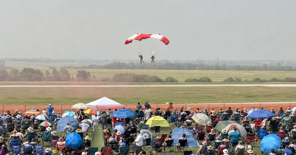
The traffic model focused on the busy minute: many spectators potentially recording a display and sharing media within the same short window.
| Project input | Planning figure | How to read it |
|---|---|---|
| Covered-zone design load | About 15,000 people | Capacity requirement, not concurrent Wi-Fi clients |
| Public event attendance | About 50,000 over two days | Whole-event figure, not the mapped-zone load |
| Planned spectator area | More than 300,000 m² | Estimate from the supplied site plan |
| Outdoor Wi-Fi 6 APs | 59 X303 units | Planned count; confirm against the final installation record |
| Outdoor 5G backhaul nodes | About 30 OG530 units | Planned count; confirm against the final bill of materials |
| Post-event telemetry | Not supplied | No measured throughput, client, or uptime claim |
These are planning figures, not a claim that 15,000 devices connected. That distinction matters when judging what the architecture was intended to solve and what still needs measurement.
What Constraints Shaped This Temporary Event Wi-Fi Design?
The plan had to solve uneven crowd density, upload-heavy bursts, temporary mounting, scattered power, and weather exposure at the same time. The open field looked simple on a map, but those constraints pulled the design in different directions.
First, the design assumed that the crowd would not be evenly distributed. Denser zones along the show line, around vendors, and near entrances needed more usable capacity than quiet areas. A uniform grid could place too much equipment in one area and too little in another.
Second, the traffic model prioritized upload. A normal guest network often carries more video down than it sends up; an air-show plan must also account for bursts of clips and photos moving outward. A backhaul that looks healthy in a download speed test can still disappoint under sustained upload demand.
Third, everything had to be temporary. Hardware, cabling, and mounts needed to go up quickly, come down cleanly, and be ready for another event. Civil works would have consumed both the schedule and the budget.
Finally, outdoor power and weather were part of the network plan. Every additional AC point meant another enclosure, connection, and failure opportunity. Rain ratings did not remove the need to protect connectors, ground the installation, and plan for wind.
How Did 5G Backhaul and Wi-Fi Access Fit Together?
The proposed pattern was simple: an outdoor 5G CPE brought internet backhaul into a local switch, and compatible PoE hardware fed two nearby outdoor access points. Across most of the site, one cluster was assigned to a small part of the crowd rather than trying to carry the whole venue.
| Network layer | Project role | What had to be validated |
|---|---|---|
| Carrier backhaul | OG530 outdoor 5G CPE brings WAN access to the cluster | Bands, SA/NSA mode, signal quality, sustained uplink, sector load |
| Local distribution | Compact switch and compatible PoE injectors distribute Ethernet and power | PoE standard, voltage, cable length, power budget, weather protection |
| Wi-Fi access | Usually two X303 outdoor APs serve the local crowd cell | Mounting height, channel reuse, transmit power, active-user demand |
| Operations | X303 web and mobile cloud management provides remote visibility | Alerts, configuration control, firmware policy, event telemetry |
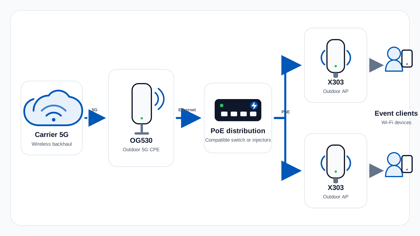
One planned cluster separates cellular backhaul from local Wi-Fi access: carrier 5G → OG530 → compatible PoE distribution → two X303 APs → event devices. The switch or injectors still need to match each device’s PoE requirements.
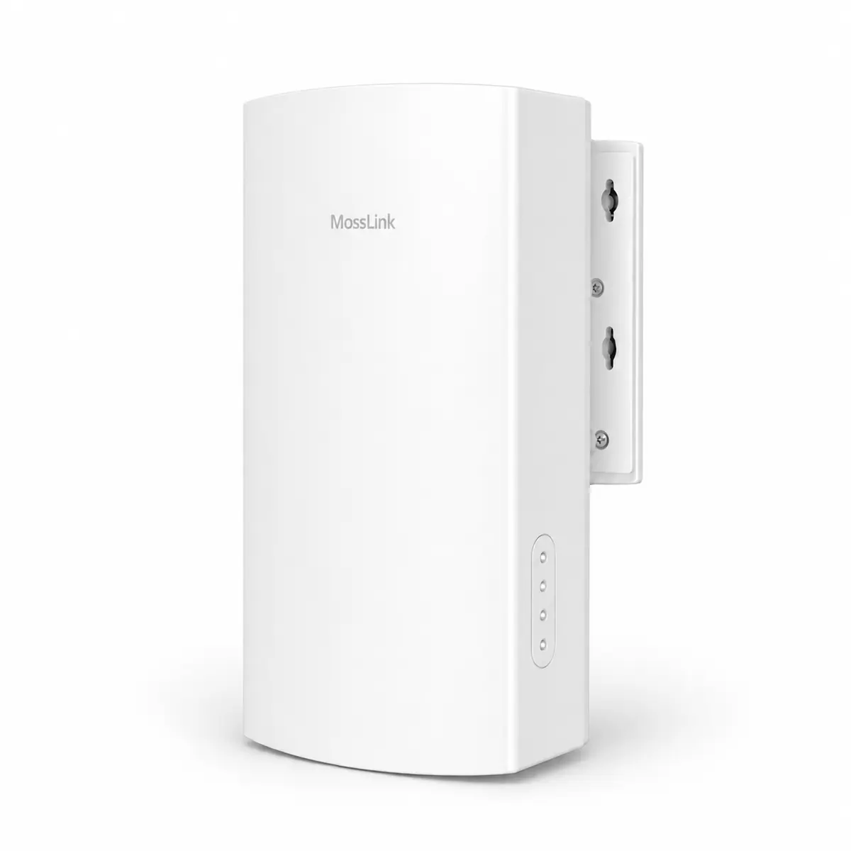
The OG530 5G outdoor CPE was specified to handle carrier backhaul. Its outdoor placement, high-gain antenna, 2.5GbE interface, and PoE input made it practical to mount where the cellular signal was better instead of leaving the modem behind walls or coated glass.
The X303 cloud-managed outdoor Wi-Fi 6 access point was specified to handle local client access. Its sealed internal-antenna design kept the pole installation compact, while dual-band Wi-Fi 6, PoE, and remote management matched the temporary build.
This distributed layout was intended to shorten the wired run between backhaul and access points and reduce the fault domain. Under the proposed topology, a problem at one CPE or switch would affect a local cluster rather than every spectator area, assuming there were no shared dependencies upstream.
There is an important limit to that idea. Thirty CPEs do not automatically create thirty independent carrier paths. Several units may still attach to the same cell or sector. The architecture spreads local network risk, but only a carrier survey can show whether it also spreads radio-access capacity. That is where an ISP and fixed-wireless CPE design perspective becomes useful.
Why Did the Plan Specify 59 X303 Access Points?
The plan specified 59 APs because it treated 100 m as a cell-placement radius rather than stretching each radio to its ideal range. The site geometry included a primary spectator zone of roughly 880 × 300 m and an additional area of about 370 × 250 m; the X303 lists an ideal outdoor coverage radius of around 150 m.
That reduction was deliberate. People, tents, vehicles, mounting height, and overlapping cells all change useful range. Planning at the ideal free-space number might have produced coverage on a drawing while leaving weak capacity where the crowd was thickest. The shorter radius was intended to create more, smaller cells with room for controlled overlap.
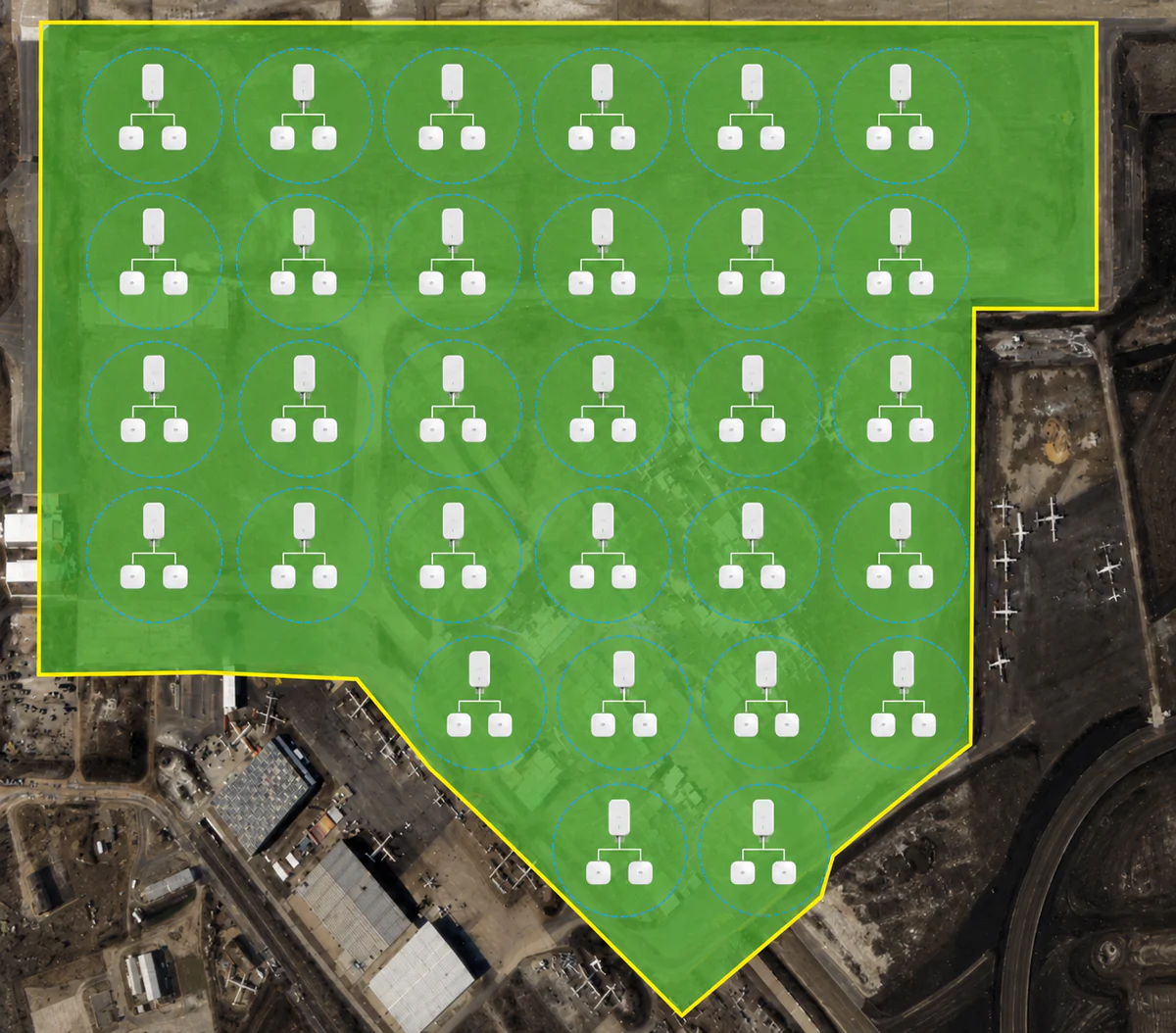
This cleaned visual preserves the supplied 30-cluster planning concept and its typical one-CPE-plus-two-AP pattern. The brief separately lists 59 APs, so the final bill of materials—not the repeated icon count—should govern installation.
The same caution applied to client counts. The planning drawings and the X303 product limits produce three very different numbers:
| Planning number | Figure | Useful meaning—not a guarantee |
|---|---|---|
| Covered-zone design load | About 15,000 people | Project requirement; not 15,000 connected devices |
| Cell-placement radius | 100 m | Site-plan assumption; not measured edge coverage |
| Maximum association ceiling | 59 × 256 = 15,104 | Maximum device associations on paper; not a throughput target |
| Recommended planning envelope | 59 × 128 = 7,552 | A more conservative starting point before RF and traffic modelling |
| Measured active clients | Not provided | Must come from controller telemetry; should not be inferred from attendance |
That arithmetic is useful, but it is not a promise of 7,552 simultaneous video uploads. Association capacity, airtime capacity, application demand, and 5G backhaul capacity are different limits. A sound event model starts with expected Wi-Fi adoption and active-user behavior, then checks whether RF airtime and backhaul can carry the busy minute—not just whether devices can join.
For a broader look at the physical variables behind that derating, the outdoor access point selection guide covers placement, weather protection, and client density. A separate real-world outdoor AP coverage test shows why detectable range and usable cell size are not the same number.
Why Plan Narrower Channels and Lower Transmit Power?
Narrower channels and controlled transmit power create more room for channel reuse and smaller, more deliberate cells. With 59 planned APs in an open area, the main RF design risk was co-channel interference: too many cells hearing one another.
The X303 can use 160 MHz channels, which is attractive in a single-AP speed test. In a dense field, that width consumes too much spectrum and leaves few opportunities for channel reuse. The RF plan therefore favored narrower channels. They reduce the peak rate of one client on paper but allow more neighboring cells to operate without talking over one another. This follows the same high-density principle described in Cisco’s large public network design guide.
Transmit power followed the same logic. Maximum power would enlarge every cell, increase overlap, and encourage phones to remain attached to a distant AP. The RF plan treated power as a cell-size control. Intentional overlap could support movement, while 802.11k/v/r could assist compatible clients between zones. The client still makes the roaming decision, so those standards help rather than guarantee a handoff.
Per-user and per-SSID rate limits were intended to protect airtime and the shared 5G uplink from a small number of heavy sessions. The design target was not the fastest isolated speed test; it was more predictable aggregate service across many potential connections.
Which OG530 5G Metric Mattered Most?
Sustained uplink at the mounting location mattered more than headline download speed because the traffic model emphasized outbound photos and video. The OG530 is offered in MediaTek T750 and Qualcomm X62 configurations. Their published 5G rates are useful for defining an upper boundary, including up to 2.5 Gbps uplink for the MediaTek version and up to 900 Mbps uplink for the Qualcomm version in 5G standalone (SA) conditions. Non-standalone (NSA) mode uses an LTE anchor and has different published limits. These are modem ceilings, not expected field throughput, and the project brief does not identify which OG530 variant was installed.
For this type of event, the more revealing measurements are sustained upload throughput, latency under load, and signal quality at the actual mounting height. It also matters whether the carrier is operating in SA or NSA mode, which bands are available, and how busy the serving sector becomes when the public arrives.
A good pre-event survey therefore tests the same traffic direction the event will create. A morning download test from an empty field can make a weak design look comfortable. Repeated uplink tests, from every proposed cluster location and at representative busy times, offer a better view.
The 2.5GbE PoE interface solves a separate physical problem. One outdoor-rated Ethernet cable can carry data and power to the CPE, so the modem can sit near the stronger signal without requiring an AC outlet on the mast.
Should the Temporary Uplink Be 5G or Satellite?
Both are valid answers on a field with no fiber, and they fail in different directions. This project specified 5G, but the choice depends on the site rather than on a general ranking.
| 5G outdoor CPE | Satellite (Starlink-class) | |
|---|---|---|
| Setup | Mast, one PoE cable, SIM, aim by app | Dish with clear sky view, mains or inverter power |
| Main risk | The cell is shared with the entire crowd | Obstruction, and a lower ceiling on uplink |
| Best case | Sites with good coverage and moderate cell load | Remote sites where cellular coverage is thin or absent |
| Contract | SIM and data plan, easily moved between events | Service plan tied to a dish |
The failure mode that catches event teams out is congestion, not coverage. A field that tests well on the build day—empty, one engineer with a phone—can degrade once the same sector is carrying every spectator’s uploads. That is the same limit described earlier: more CPEs do not create more carrier capacity. Where the event matters, redundancy usually means different failure domains rather than more of the same: a 5G CPE as primary with a satellite link as backup, or CPEs split across two operators’ SIMs.
The satellite side of that pairing is covered separately in the guides on distributing a satellite uplink over distance and choosing an access point to extend a satellite link outdoors.
What Could PoE and Cloud Management Change in the Build?
PoE could reduce field power runs, while cloud management could reduce visits to elevated APs. Power over Ethernet carries power and data over one cable to supported devices, but the final switch, injector, AC, and DC topology still needs to be verified against the bill of materials, including the voltage and PoE standard required by each device.
Power still needed honest budgeting. At the X303’s published ceiling of less than 18 W, 59 APs can approach 1.06 kW. About 30 OG530 units at less than 10 W add up to another 300 W. The radios alone can therefore approach 1.36 kW before switch consumption, conversion loss, cable loss, and reserve capacity are added.
The X303’s IP67 enclosure and -30°C to +60°C operating range suited an exposed temporary installation. The documented OG530-M enclosure is IP65. Those ratings address dust and water ingress at the device body; they do not replace sealed cable entries, strain relief, surge protection, grounding, or wind-safe mounting.
Once the APs were elevated, cloud management could reduce physical revisits. Operators could monitor status and make SSID, channel, power, and firmware changes from a web dashboard or mobile app. In a secured or crowded venue, avoiding a mast climb is an operational benefit, not a cosmetic feature. The remote access point management guide explains the operational questions worth checking before rollout.
Can the Public Network Be Portal-Authenticated or Voucher-Billed?
It can, and events are one of the places where it pays for itself. A captive portal on the public SSID gives the organizer a branded splash page—schedule, site map, sponsor placement, safety notices—and an opt-in list that has value beyond the event weekend. Terms-of-use acceptance on the same page is also the cleanest way to handle liability on an open network.
Vouchers add a paid or privileged tier where one is justified: a higher-rate SSID for a press pen, broadcast crews, or vendor stands that need card payments and uploads without competing for airtime with the public network. The rate limits do the enforcement; the voucher only decides which bucket a device lands in.
Neither feature removes the capacity questions above. A portal changes who gets on and under what terms; it does not add uplink. The captive portal troubleshooting guide covers the failure modes worth expecting, and the guide to voucher-based public hotspots covers how the commercial side is usually structured.
What Should Be Configured Before the Equipment Ships?
Field time is for mounting and cabling, not configuration. On a build with a short window and elevated mounts, the items below are better finished and tested in the warehouse—the approach described in pre-configuring a network before overseas deployment.
- SSIDs and VLANs staged on every AP, identical across the fleet, with the public SSID rate-limited and isolated.
- Cloud binding completed, with every serial number already visible in the dashboard.
- Firmware aligned on one version across all units—no mixed builds.
- SIM tested in the actual CPE, with APN, PIN, and data plan confirmed, plus a spare SIM on a second operator.
- PoE budget checked against the real AP count, with the generator feed sized for the switch, lighting, and everything else in the tent.
- Cable lengths measured per mast run, terminated and tested, with outdoor-rated Cat6 and drip loops at the connectors.
- Mounting hardware matched to the actual masts, scaffold, or truss on site—pole clamps are among the most commonly forgotten items on a packing list.
- A labeled, photographed pack-down list so strike day returns the same kit that left, ready for the next event.
What Does the Available Evidence Prove—and Not Prove?
The available evidence proves that the supplied design addressed a no-fiber spectator zone with a modular 5G-to-Wi-Fi architecture. It does not prove the number of active users, field throughput, or uptime. The planned equipment count, PoE distribution, and recoverable mounts addressed the physical build constraint, while the 5G backhaul plus Wi-Fi 6 edge pattern was intended to keep each cluster to a manageable size.
What the available brief does not show is just as important. It does not include peak associated clients, active clients, total uploaded traffic, 95th-percentile uplink per cluster, channel utilization, retry rates, or incident history. Without those controller and CPE records, it would be inaccurate to say that the 15,000-person design load became 15,000 Wi-Fi users or that the full planning envelope was reached.
Those missing numbers are not merely material for a stronger case study. They are the feedback loop for the next event. They show where a cluster was oversized, where the carrier became the bottleneck, where an AP needed a different channel, and whether the next deployment needs more radios or simply better placement.
Where Else Does This Architecture Fit?
The pattern can fit sites that need large-area coverage, have a short deployment window, and have usable carrier capacity but no fixed backhaul. Examples include outdoor concerts, agricultural fairs, marathons, seasonal campgrounds, construction compounds, and temporary emergency coordination sites.
It is not a universal substitute for fiber. If the carrier sector is already congested, adding more CPEs may only divide the same limited resource. If the site will remain for years, fiber may have the better lifecycle cost. The value of the 5G cluster model is speed, modularity, and recoverability—not a claim that cellular backhaul always wins.
For the Wi-Fi edge, MossLink’s outdoor AP deployment options show how antenna pattern, client density, management, and mounting change across more permanent sites.
What Is Worth Checking Before Reusing This Design?
Start with site geometry, expected crowd distribution, upload demand, carrier capacity, and available power; the equipment count comes later.
- Map crowd density and upload-heavy moments, then size cells below ideal datasheet range where people and structures will absorb signal.
- Test sustained 5G uplink at every CPE location and record the serving cell or sector; nearby units may still share capacity.
- Plan channel reuse and transmit power before opening the network to users.
- Separate association limits from active-user throughput and backhaul capacity.
- Include CPEs, switches, cable loss, conversion loss, and reserve margin in the power plan; verify every PoE voltage and standard.
- Protect connectors, grounding, strain relief, and mounts, then capture controller and CPE telemetry for the next design.
How Do OEM and ODM Options Change This Build?
MossLink builds these products as an outdoor access point OEM/ODM manufacturer, and event and rental operators are one of the groups that benefit most from customization: enclosure colour and silkscreen that survives being handled by riggers, firmware defaults that come up in a standard SSID and VLAN scheme out of the box, and private-label packaging for rental inventory. A fully white-labeled cloud platform is available as a separately scoped OEM program with a one-time setup fee and a committed-volume MOQ, rather than as a default feature of every model.
If you are planning temporary Wi-Fi for an event, work site, or seasonal venue, share the site dimensions, expected attendance, power locations, and available carriers with MossLink. We can help turn those inputs into a cluster plan using the X303, OG530, and the appropriate PoE hardware—without pretending one equipment count fits every field.
Featured in this guide
Frequently Asked Questions
Practical answers for planning a similar network.
How can temporary event Wi-Fi work without fiber?
Why pair an OG530 5G CPE with X303 outdoor access points?
How many access points does a 15,000-person event zone need?
Does the OG530's maximum 5G speed predict event performance?
Should temporary event Wi-Fi use a 5G CPE or a satellite uplink?
Can everything be configured before the equipment ships to the site?
How many users can one X303 outdoor access point support?
Deploy with confidence
See how MossLink builds ISP CPE & Hotspot Deployment Solution end-to-end
Network architecture, products used, and real-world results in one place.
Tags
Share