In recent months, one of our customers ran into a PoE compatibility issue during an outdoor wireless bridge deployment. As a sales engineer at MossLink, I want to share the real project experience so other installers, WISPs, and security integrators can identify the same problem quickly and avoid wasted troubleshooting time.
Many users believe:
“If a wireless bridge supports both 24V passive PoE and standard 48V PoE, it should work with all PoE switches.”
In real projects, PoE compatibility is more complicated than that.
The Customer’s Actual Problem
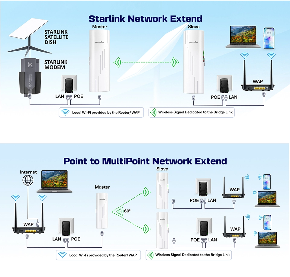
The customer was building an outdoor surveillance link with the following equipment:
| Device | Model |
|---|---|
| Wireless Bridge | MossLink WB610H |
| PoE Switch | Uniview (UNV) standard 48V PoE switch |
| Deployment | Outdoor surveillance bridge project |
After connecting everything:
- The PoE switch appeared to be operating normally
- The Ethernet cable tested fine end-to-end
- But the wireless bridge would not start — no LEDs, no link
At first, the customer suspected the usual culprits: hardware failure, unstable power, a bad cable, or incorrect PoE voltage. After detailed analysis on our side, the real reason turned out to be much deeper — and it is not unique to this one project.
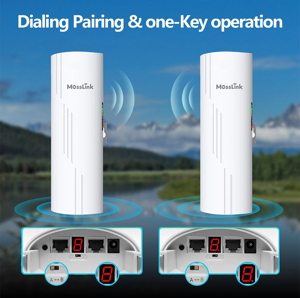
How Does Mosslink Wide-Voltage PoE Work?
The current MossLink WB610H wireless bridge supports wide-voltage PoE input.
| LAN Port | Supported Power Input |
|---|---|
| LAN1 | Passive PoE 24–53V via pins 4-5-7-8 |
| LAN2 | Passive 24–53V via 4-5-7-8 or standard PoE via 1-2-3-6 |
| Simultaneous 8-core input | Not supported |
In other words, the bridge accepts power on either the 1-2-3-6 pair or the 4-5-7-8 pair — but not both pairs energized at the same time.
This is actually very common in the wireless bridge market today.
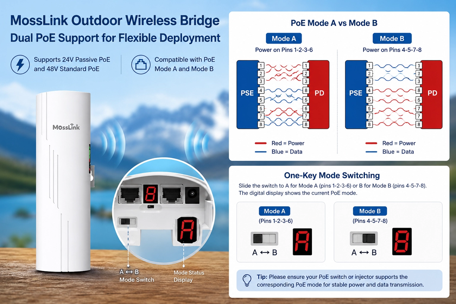
What Are Mode A and Mode B in PoE?
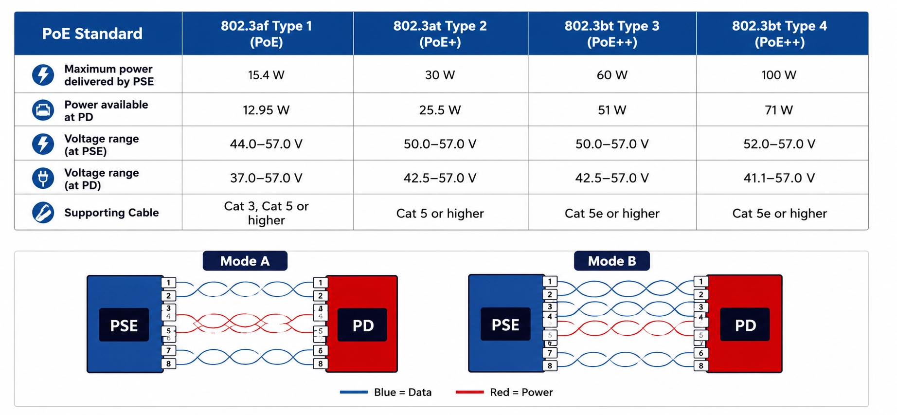
In standard PoE systems there are two common ways to deliver DC power over a Cat5e/Cat6 cable.
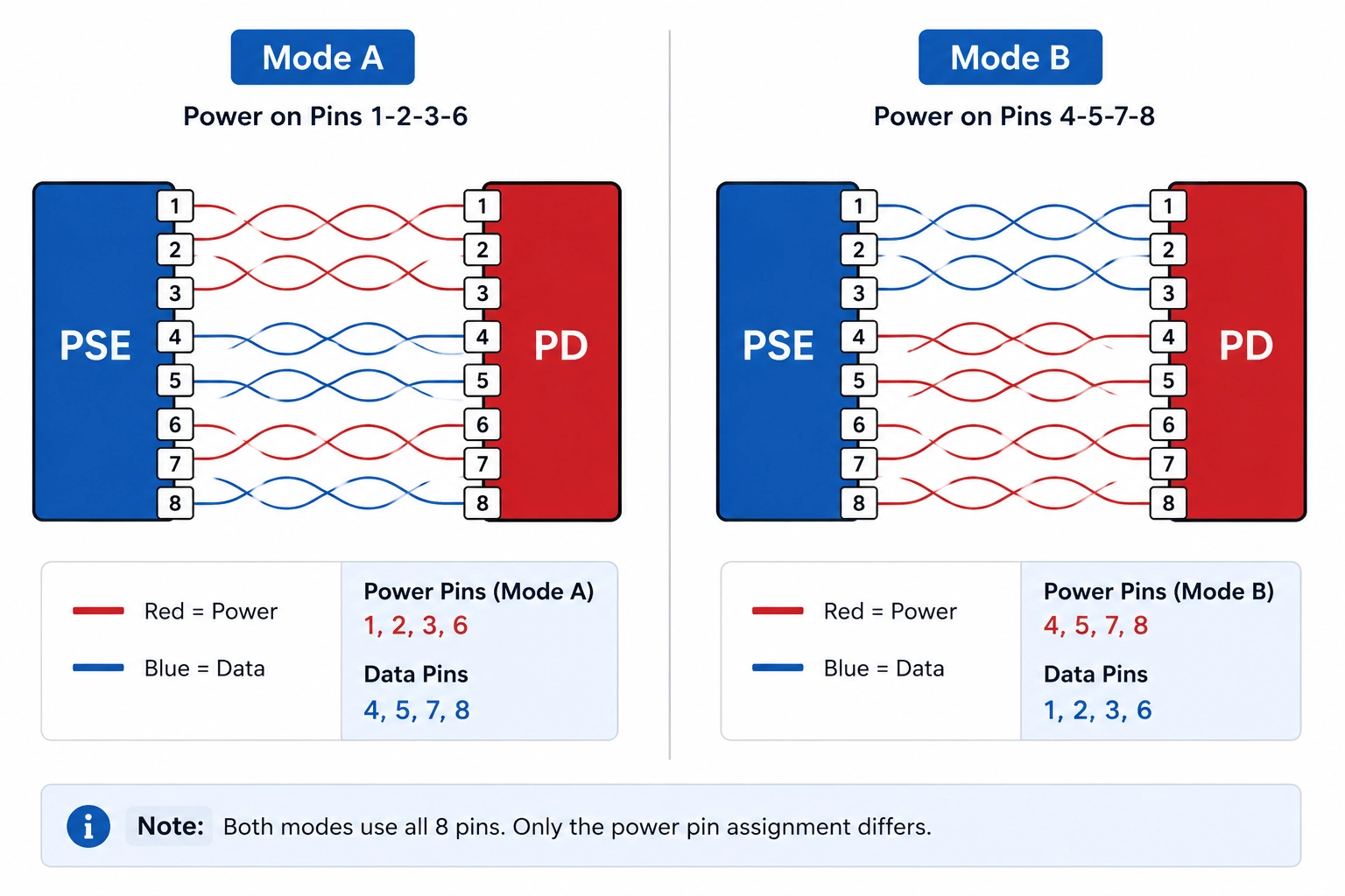
Mode A
| Feature | Details |
|---|---|
| Power pins | 1-2 / 3-6 |
| Data transmission | Shared with power |
| Common in | Standard enterprise PoE switches |
| IEEE type | End-Span |
Mode A is the most common method used in enterprise PoE switches today (TP-Link, Cisco, Ubiquiti, H3C, and most managed PoE switches).
Mode B
| Feature | Details |
|---|---|
| Power pins | 4-5 / 7-8 |
| Data transmission | Separate from power |
| Common in | Passive PoE systems |
| Typical devices | Wireless bridges, outdoor CPEs, mid-span injectors |
Many passive PoE products and bundled CPE injectors use Mode B because the spare pairs are easier to work with on low-cost PCBs.
Why Did the Uniview (UNV) PoE Switch Cause Compatibility Problems?
After testing the customer’s switch on our bench, we found the actual behavior:
The Uniview (UNV) PoE switch outputs power on both 1-2-3-6 and 4-5-7-8 simultaneously.
This is effectively 8-core power output.
However:
- The WB610H currently supports single-mode power input only
- It does not support simultaneous dual-pair power injection
The result on the PD side is that the power circuit cannot initialize properly, and the bridge fails to boot.
Why Do Most Wireless Bridges Still Not Support 8-Core PoE?
Many integrators assume that “standard PoE devices should always be compatible.” The market reality is different.
| Product Type | Typical PoE Support |
|---|---|
| Low-cost outdoor CPE | 4-5-7-8 only |
| Standard enterprise bridge | 1-2-3-6 only |
| Wide-voltage bridge | 1-2-3-6 or 4-5-7-8 |
| Full 8-core compatible bridge | Rare |
More than 90% of wireless bridges on the market still only support single-mode PoE input. The reason is hardware cost — full 8-core compatibility requires:
- More complex PCB routing
- Additional power management ICs
- Higher BOM cost
- More difficult thermal management
At the price point most outdoor bridges compete on, that margin matters, and most vendors trade compatibility for cost.
Why Most Standard PoE Switches Usually Work
Most standard PoE switches on the market use only the 1-2-3-6 pair (standard Mode A). Against that majority, the WB610H works normally — LAN2 picks up the 48V on 1-2-3-6 and the bridge boots as expected.
The compatibility problem appears with vendors who energize both pairs at the same time — most notably certain Uniview (UNV) models, with selected Hikvision DS-3E and Dahua PFS3000 SKUs behaving the same way. These switches are concentrated in CCTV verticals where they are paired with our wireless bridges, which is exactly where this issue surfaces.
How Will Mosslink Solve This Problem?
To improve compatibility with more enterprise PoE switches, MossLink is already developing the next-generation mainboard.
| Upgrade Item | Improvement |
|---|---|
| New PCB design | Optimized dual-pair power routing |
| Additional power ICs | +2 PoE PD management ICs |
| 8-core input support | Yes |
| Wider compatibility | Full support for enterprise + CCTV PoE switches |
Future revisions will accept:
- 1-2-3-6 power input
- 4-5-7-8 power input
- Simultaneous 8-core PoE input
This will significantly improve compatibility in:
- Surveillance projects
- WISP deployments
- Industrial wireless transmission
- Outdoor bridge applications such as elevator and campus links
The new mainboard targets sample release in Q3 2026 and will roll into the WB610H line first, then the WB630 and WB530 lines on their next refresh.
How Can Installers Avoid Similar Problems?
1. Confirm the PoE output method of the switch
Before deployment, check whether the switch uses Mode A, Mode B, or simultaneous dual-mode output. A pocket RJ45 PoE tester ($10–15) or a multimeter across pins 1-2 vs 3-6 and 4-5 vs 7-8 will tell you in under 90 seconds.
2. Do not assume “standard PoE” means universal compatibility
Different manufacturers implement PoE differently. Even when both devices claim “48V standard PoE,” there can still be pinout-level compatibility differences.
3. Test using the original PoE injector
This is often the fastest troubleshooting method. If the bridge works with its bundled injector but fails with the switch, the issue is almost always PoE compatibility on the PSE side — not the bridge.
4. Choose bridges with better wide-voltage design
For complex projects — outdoor surveillance, industrial networking, long-distance backhaul, elevator wireless transmission — pick devices that explicitly support:
- 24V passive PoE
- 48V standard PoE
- (Future) full 8-core compatibility
Recommended MossLink Wide-Voltage Wireless Bridges
| Model | Main Features | Recommended Applications |
|---|---|---|
| WB610H | Wide-voltage PoE / cost-effective | Outdoor surveillance |
| WB630 | Long-range wireless bridge | Industrial deployment |
| WB530 | Compact outdoor bridge | Security projects |
For related field issues, see our guide on choosing a wireless bridge for CCTV backhaul — PoE Mode A/B compatibility is one of the six most common failures we cover there.
Talk to Our Engineers on WhatsApp
See the WB610H Wide-Voltage Bridge
Plan the complete link
Get a point-to-point wireless bridge kit recommendation
Tell us the distance, throughput, power source, and deployment environment. We will match the bridge pair, PoE, outdoor cable, and mounting accessories.
Continue Planning Your Wireless Link
Deploy with confidence
See how MossLink builds Outdoor CCTV Wireless Backhaul Solution end-to-end
Network architecture, products used, and real-world results in one place.
Tags
Share