A bridge installation company in South Africa told us their callback rate dropped from 35% to under 5% when they started using a pre-deployment checklist. The most common reason for callbacks: alignment drift within 48 hours because the mount hardware was not tightened properly. Second most common: water ingress at the Ethernet connector because the installer forgot the weatherproof boot.
These are not equipment failures. They are skipped steps. This checklist covers every verification an installer should complete before leaving the site.
What Should You Check Before Leaving the Office?
1. Confirm line of sight
Use Google Earth or a mapping tool to draw a straight line between the two installation points. Check for obstacles: buildings, trees, terrain ridges, construction cranes.
Then go to both sites and visually confirm. Maps do not show new construction, seasonal foliage, or temporary structures.
If you cannot see the other end from your installation point, the bridge will not work reliably. Partial obstruction reduces signal; complete obstruction kills it.
2. Calculate Fresnel zone clearance
Line of sight is necessary but not sufficient. The radio signal travels in an elliptical zone (Fresnel zone) around the direct path. Obstructions inside this zone degrade signal even if the direct line is clear.
First Fresnel zone radius at midpoint:
| Distance | Frequency | Fresnel Radius at Midpoint |
|---|---|---|
| 1km | 5.8GHz | 2.3m |
| 3km | 5.8GHz | 4.0m |
| 5km | 5.8GHz | 5.2m |
| 10km | 5.8GHz | 7.3m |
| 20km | 5.8GHz | 10.4m |
At 5km on 5.8GHz, the Fresnel zone is a cylinder 10.4m in diameter at the midpoint. A tree canopy that tops out at 8m might not block line of sight but it intrudes into the Fresnel zone and costs you 6-10dB of signal.
Rule: 60% Fresnel zone clearance is minimum. 80% is recommended. Mount higher if obstacles intrude.
3. Check regulatory restrictions
Before deploying 5.8GHz bridges, verify:
- Maximum EIRP allowed in your country (typically 30-36dBm on 5.8GHz)
- DFS channel requirements (5.25-5.725GHz requires radar avoidance)
- Licensing requirements (some countries require registration for fixed links above certain EIRP)
In many African countries, 5.8GHz is unlicensed with generous EIRP limits. In the EU, DFS channels require specific firmware compliance. Know before you install.
4. Pack the complete kit
Do not discover missing hardware at the top of a tower. Pack:
- Bridge units (2x, firmware pre-updated)
- PoE injectors (2x, one per end)
- Mounting brackets and hardware (stainless steel)
- Weatherproof Ethernet connectors or boots
- Grounding kits (ground wire, clamp, rod)
- Pre-made Ethernet cables (outdoor-rated, correct length)
- Cable ties and adhesive mounts for cable management
- Laptop with browser for bridge configuration
- Binoculars (for verifying line of sight to distant end)
- Phone/radio (for communicating between installation teams at each end)
What Should You Verify at the Installation Site?
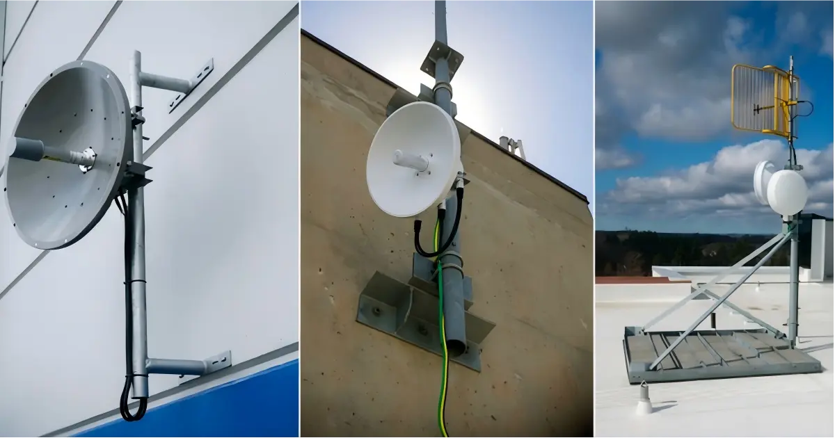
5. Inspect the mounting structure
The bridge mount must be rigid. Any flex or sway translates directly to signal instability.
Pole mounts:
- Minimum 50mm (2-inch) diameter steel pole for bridges up to 20dBi
- Minimum 75mm (3-inch) diameter for high-gain dishes above 25dBi
- Guy wires for any pole above 6m
- Concrete base or ground anchors rated for local wind speeds
Wall mounts:
- Verify the wall material can hold the bracket and bridge weight (including wind load)
- Use through-bolts on hollow walls, expansion anchors on concrete
- Ensure the bracket allows azimuth and elevation adjustment
Existing tower:
- Check tower loading capacity before adding equipment
- Use proper tower climbing safety equipment
- Mount at least 1m away from other antennas to prevent near-field interference
6. Install grounding
Lightning protection is not optional for any bridge mounted above 3m.
Proper grounding sequence:
- Drive a ground rod (minimum 1.5m copper-clad steel) into the soil at the base of the pole
- Run 10AWG (minimum) copper ground wire from the bridge mounting bracket to the ground rod
- Connect the bridge’s grounding lug to the ground wire
- Ground the PoE injector’s Ethernet shield at the indoor end
The WB503H and WB730 include 2kV lightning protection on the Ethernet port. The WB5axH6-35 includes 6kV protection. But this protection only works if the current has a path to ground. Without proper grounding, the surge has nowhere to go except through your equipment.
7. Run and protect cables
Outdoor Ethernet cables must be UV-resistant and waterproof. Standard indoor Cat6 degrades in direct sunlight within 6-12 months.
Cable routing rules:
- Use drip loops before the cable enters any enclosure (water runs down the cable and drips off the loop instead of entering the connector)
- Secure cables every 60cm along the pole with UV-resistant cable ties
- Leave 30cm service slack at the bridge end for future maintenance
- Apply weatherproof boots or self-fusing tape on all outdoor Ethernet connections
The number-one cause of bridge failure after installation is water ingress at the Ethernet connector. A $2 weatherproof boot prevents a $500 bridge replacement.
8. Power on and verify basic connectivity
Before alignment, power on both bridge units and verify they establish a link:
- LED indicators show link status
- Web UI accessible from the PoE injector’s LAN port
- Both units see each other (check association table)
If units do not link, verify:
- Both are on the same channel and SSID
- Both are in the correct mode (one AP/Base, one Station/Client)
- Firmware versions match (mismatched firmware can prevent association)
How Do You Align a Wireless Bridge?
9. Coarse alignment
Point both bridge antennas at each other using visual reference (binoculars help at distances above 2km). Tighten the azimuth (horizontal) adjustment to roughly the correct bearing.
For dishes above 25dBi (beam width under 6 degrees), coarse alignment needs to be within 3 degrees to establish any link. For flat panels at 14-20dBi (beam width 10-15 degrees), coarse alignment is much more forgiving.
10. Fine alignment
With both units powered on and a link established:
- Adjust one end at a time. The other end stays fixed.
- Slowly pan the antenna in azimuth (horizontal) while watching signal strength on the web UI or LED display.
- Find the signal peak. Mark it. Overshoot slightly, note the signal, come back to peak. This confirms you found the true center, not a side lobe.
- Lock the azimuth bolt.
- Repeat for elevation (vertical).
- Repeat the entire process at the other end.
- Re-check the first end — adjusting the second end may have shifted the optimal alignment.
Signal strength targets:
- Above -55dBm: excellent — link will be rock-solid
- -55 to -65dBm: good — reliable for most applications
- -65 to -70dBm: acceptable — monitor for degradation in rain
- Below -70dBm: re-align or check for Fresnel zone obstruction
11. Tighten everything twice
After alignment is complete:
- Tighten all mount bolts to specified torque
- Wait 5 minutes
- Re-check signal strength — if it has shifted more than 2dB, the mount is flexing. Tighten again or reinforce the mount.
- Apply thread-locking compound (Loctite or equivalent) on all bolts exposed to weather
The most common callback issue: installer finger-tightens the bolts, signal looks good, leaves the site. Within 48 hours, thermal expansion and wind vibration loosen the bolts, the antenna shifts 1 degree, and the signal drops 10dB.
12. Document and test
Before leaving the site:
- Record signal strength at both ends (screenshot the web UI)
- Record channel, TX power, and link speed
- Run a speed test (iPerf or similar) in both directions for 5 minutes
- Record GPS coordinates of both installation points
- Photograph the installation at both ends (for warranty and future maintenance reference)
- Verify the PoE injector location is accessible and labeled
- Confirm weatherproof boots are installed on all outdoor Ethernet connections
- Confirm cable drip loops are in place
Leave a copy of the installation record with the customer. If a problem occurs 6 months later, having the original signal strength on record tells the technician whether the issue is alignment drift, new obstruction, or equipment failure.
For bridge model selection by distance and use case, see our CCTV wireless bridge buying guide or wireless bridge vs fiber comparison.
Next Steps: Prepare Your Bridge Installation
Before climbing the tower:
- Confirm line of sight — use Google Earth to check, then verify in person at both sites
- Calculate Fresnel zone — ensure 60% clearance minimum at the midpoint; mount higher if trees or terrain intrude
- Pack the full kit — use the checklist in step 4 above; missing a $2 weatherproof boot causes a $500 callback
- Choose your bridges — see our CCTV wireless bridge buying guide for model selection by distance
Need installation support? Our engineers can review your site survey and recommend mounting heights, channel plans, and equipment.
Tags
Share